Designing plastic parts for Injection Molding is critical to address application requirements. It is a complex task involving many factors that can minimize molding problems
in a logical manner.The following information is an overview of the most important elements for injection molded parts .

Selecting A Parting Line

The parting line,where the two halves of the mold come together,is one of the important factors to consider when designing parts to be injection molded.It determines the direction of your draft. Generally, it is usually not a good idea to place the parting line on a filleted surface,which would require a tight tolerance mold with an increasing cost. Any mismatch will lead to flash and a potential cosmetic defect. Placing your parting line on sharp edges is the most ideal placement.

Adding Draft and Radii to Injection Molding Designs

An injection molding design needs to ensure the part comes out of the mold without damage or too much resistance. Applying draft and radii to a part is of vital importance to a properly designed injection-molded part. A part can be released better from a mold with less drag on its surface at the help of draft because the material shrinks onto the mold core. An excessive amount of pressure on the ejection system is required when the draft is limited,which is likely to damage parts and the mold. Angling the walls of the part from the parting line(drafting) is necessary to avoid these issues.

Uniform Wall Thickness

Uniform wall thickness is key to plastic injection molding,which helps manage cosmetics,weight and strength of the part. Material flow in the cavity can be kept consistent and even cooling can be made as well by controlling wall thickness.Inconsistent wall thickness can cause pressure spikes,material degradation,too high of differential pressure across the part,and poor process control.Consideration of acceptable stress and the expected lifetime of the part should help establish the nominal or minimum wall thickness. To improve your production efficiency,we offer you the following information for consideration.

RECOMMEND WALL THICKNESS FOR COMMON RESINS

(Remember this is only a general rule.)

Resin Inches
ABS 0.045 – 0.140
Acetal 0.030 – 0.120
Acrylic 0.025 – 0.150
Liquid crystal polymer 0.030 – 0.120
Long-fiber reinforced plastics 0.075 – 1.000
Nylon 0.030 – 0.115
Polycarbonate 0.040 – 0.150
Polyester 0.025 – 0.125
Polyethylene 0.030 – 0.200
Polyethylene sulfide 0.020 – 0.180
Polypropylene 0.025 – 0.150
Polystyrene 0.035 – 0.150
Coring and Ribbing

Coring and and ribbing should be taken into consideration to increase a part’s design integrity and its load bearing capacity. Both of them can reduce cycle time,reduce part weight,and could make the part stronger.Coring out your thick part will increase the part’s performance and cosmetic appearance without necessarily sacrificing performance.Typically,it is ideal to use a rib-to-wall thickness ratio of 40 to 60 percent the thickness of adjacent surfaces.The main body of the part should be designed thick enough to better reduce sink and stresses that can create warp in your part.

Core-Cavity

The core and cavity are often referenced as the A and B sides or top and bottom halves of a mold. A core-cavity approach to part design can manufacture parts in a cost-efficient way. It means you can improve the overall cosmetics while saving time and money,because it keeps a consistent wall thickness,maintains the part integrity and improves the strength and moldability in a lower cost.

Undercuts

Undercuts will increase the complexity and cost of the tool injection mechanisms. Adding in pass-thru coring is a good option to reduce undercuts. However,external undercuts are the easiest and most cost-effective as we accommodate through pin-actuated side-actions. These side-actions move in sync with the mold as the mold opens and closes,while the cam moves along the angled pin.

Gating and Ejection

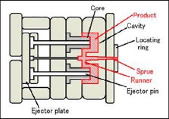
Gating and ejector pins play an important role in the process that plastic resin strategically enters the mold and plastic parts are effectively ejected from the mold.Different gates types are suitable for different applications.There are 4 types of gates used in injection molding:

Edge gates

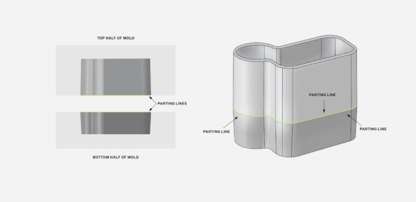
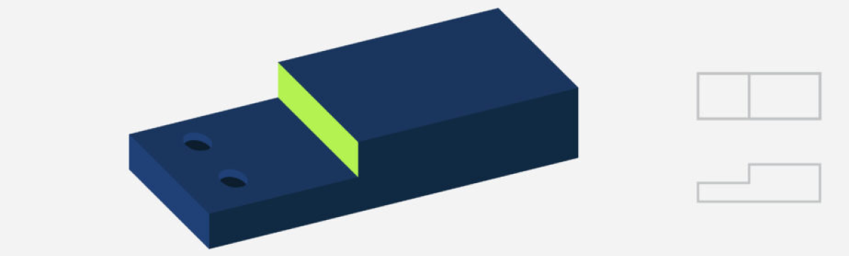
Edge gates are best suited for flat parts. Located at the edge,they inject material at the parting line of the two halves of the mold . This type of gates will create a scar on the parting line.
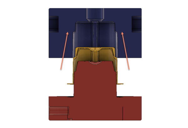
Sub-gates

Sub-gates are common but require ejector pins for automatically trimming.This type of gates generally can decrease the size of the vestige left on the exterior of the part. They have different variations,including banana gates,smiley gates,and tunnel gates.They are generally used by incorporating a tunnel gate into the side of the part or into an ejector pin (post gate).

Hot tip gates

Hot tip gates are located at the top of the mold,and are only used with hot runner injection molds. This type of molds are ideal for large scale production with minimal part waste from sprue and runner systems.Therefore,they are often the most cosmetically appealing gate.

Sprue gates

Direct or sprue gates are used for single-cavity molds that are typically large and cylindrical. The diameter of the gates is large, which is difficult to manually remove,and a fixture that is removed by milling is required. As a result,sprue gates can leave a large scar at the point of contact.

Table of Contents
Collapse
Page navigation